Hebei Tengtian Welded Pipe Equipment Manufacturing Co., Ltd.


Classification


Slitting and cut to length line
Category:
Details
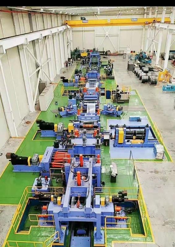
Slitting and cut to length line General introduction
1.1 Slitting and cut to length line Overview
This unit is a brand new equipment designed and manufactured according to the requirements of the demander. The steel used is selected from the products of large national famous brands. The supporting mechanical, hydraulic, and electrical components are domestically produced high-quality products that have been proven through years of practical testing. The hydraulic system uses an integrated valve block hydraulic system and an automatic unloading circuit. Can realize local automatic control. The electric control system is controlled by PLC and full digital DC speed regulating device.
This unit is a high-precision wide-width large-wall thickness vertical and horizontal shear combined unit designed and manufactured by our company that fullyabsorbs the advanced technology of similar units at home and abroad and combines actual production experience.
This unit is designed and manufactured in accordance with green environmental protection and safety standards. The overall equipment is intelligent, automated, energy-saving, environmentally friendly and safe.
It realizes centralized control of the unit, saves labor and efficiency, separates man-machine, low maintenance, and easy maintenance, and saves production costs for enterprises.
1-2. Key component materials, manufacturing processes and manufacturing accuracy 1-2. 1-2-1. All welding parts of this unit are annealed after welding
to eliminate internal stress to ensure that the parts have high mechanical strength and accuracy stability
inch leveling rollers, cutter shafts, hollow shafts are made of high-quality alloy steel 42CrMo forging.
1-2-3. Adopting active shearing method, the burr on the edge of the steel strip is small and the tensile deformation of the steel strip is small.
1-3. The company is dedicated to the design and development of slitting units, perfecting equipment from production practices, and continuously providing industry-leading slitting equipment to customers at home and abroad with excellent quality and thoughtful service.
Slitting and cut to length line Product, production capacity and overall technical parameters
1. Raw Material
1.1 The raw materials used for production are high-quality hot-rolled strip coils
1.2 Implementation standards Industry Standard
1.3 Grade HR CR GI roll coil
1.4 Material Specification
coil OD:φ800-φ2000 mm
Coil ID: Φ508 Φ610,Φ760 mm
coil width:600-1600 mm coil thickness:1.4-10.0 mm coil weight:25 ton
1.5 slitting specification and precision
1.6 cut to length main parameters:
1) raw material specification:hot rolled coil,material Q345B
Slitting and cut to length line Equipment technical specifications
1. Slitting and cut to length line summary
This unit is a mechanical, electrical and hydraulic integrated product, with a series of advantages such as advanced technology, mature technology, convenient operation, simple maintenance, sophisticated manufacturing and high degree of automation.
The purpose of this unit is to feed the steel strip with a thickness of 10mm and a width of 900 to 1600mm, cut off the head and tail after feeding, unwinding and leveling, and then feed the steel strip to the disc slitter by a leveler. According to the needs of the production process, slitting is cut into steel strips of certain specifications, which are then unloaded and packed after loop buffering, tension winding, and finally stored for storage.
The whole line of the unit adopts PLC electrical control system, DC full digital speed regulation
2. Equipment functions and performance parameters
2.1 Equipment functions and technical characteristics 2.1.1 Equipment functions
2.1.1 Slitting and cut to length line unit is used to cut the rolled steel
plate into several steel strips with a certain width along the length direction, and then wind it into steel strip coils to prepare billets for various processes such as rolling welded pipes and cold-formed steel.
2.1.2 Equipment process technical characteristics The unit is designed with multiple mechanisms for high-strength thick-wall materials to ensure the normal and stable production of the production line. The unit uses hydraulic and pneumatic systems in many places, which can realize local automatic control. The electrical part adopts PLC control and full digital DC speed regulating device, which can realize the linkage and self-locking of the whole process. The operation of the whole unit is simple, the labor intensity of the workers is low, and the maintenance is convenient.
2.2 Main technical performance parameters Belt speed:6m/min
Min slitting width:100mm Slitting width tolerance:±0.5mm
凸 Slitting burrs and bosses:≤0.25mm
Longitudinal tolerance:(side bend)≤0.1mm/m (10mm/10m)
Slitting and cut to length line Winding accuracy:Amount of staggered edges:≤2.0mm
Equipment control level
3.1. Smooth process connection between various equipment, reducing labor intensity of on-site operators
3.2. Equipped with spray device and return water system, effectively suppress dust and reduce
3.3. The roll-up and unwinding alignment is the benchmark of the unit, and the hydraulic floating centering device ensures that the steel coil is at the center line of the unit
3.4. Speed control and speed matching
The speed control of this unit is mainly the coiler and disc shear. The disc shear speed adopts DC digital horizontal line speed. The coiler speed and the disc shear speed are synchronized. The speed control of the coiler adopts a direct dynamic calculation of the coil diameter, so that the coiler automatically and dynamically adjusts the rotation speed of the motor in real time during the coiling process, thereby ensuring constant linear speed coiling. The roll diameter is calculated based on the empty tube diameter, plate thickness and speed. Its plate thickness and empty tube diameter can be set through the touch screen. The DC governor of this system uses European series products.
3.5. Tension control
The tension control of this system is realized by manually adjusting the reduction amount of the tensioner, which is also the commonly used method of thick plate longitudinal shear. Can fully meet the unit's requirements for tension control.
3.6. The unit's cylinders are all damped, with low impact, low vibration in the hydraulic circuit, and long cylinder seal life.
3.7. Slitting and cut to length line Speed control point position
The speed control point of this system is the disc shear. The speed of the coiler is dynamically adjusted according to the change of the coil diameter
Slitting and cut to length line Technical parameters of each item of equipment
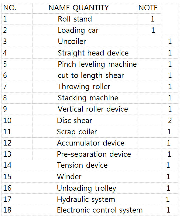
Production line equipment list
19 Anchor bolts and embedded parts
20 Throwing roller
Not included in delivery
1) Installation cables, wires, etc.
2) Tools for installation
Foundation construction and required materials
4) fence, etc.
5) Maintenance welding machine, oxyacetylene cutting device, etc.
6) Auxiliary materials such as hydraulic oil for test run
7) The embedded board is prepared by the buyer, and supplied by the supplier 4.1 prepare table
4.1.1. function
Temporarily store the tape for continuous entry into the unit to roll up the unwinder
4.1.2. position
Coiling stand is located at the forefront of the production line.
4.1.3. composed by
Composed of 1 set of material table The material platform consists of two steel frames installed on the ground
4.1.4. Technical parameters and structure Adapt to strip width: 1100~1600mm Adapt to roll weight: Max. 25t
Adapt to outside diameter of tape roll: φ800~φ2000mm Number of coil: 1 个pcs
Note : Coil width less than 1100mm should be stocked directly on the coil car
4.2. loading car
4.2.1 function
Transporting the coil from the unwinding station to the unwinder
4.2.2 postition Roller side
4.2.3 composed by
The steel coil trolley is composed of a traversing trolley, a lifting device, a bearing saddle and a track.
4.2.4 Technical parameters and structure
The traversing trolley is a welded steel structure trolley, which is driven forward or backward by a motor. The lifting device and the load-bearing saddle are welded structures. The lifting device is driven by a hydraulic cylinder to raise and lower, and is guided by 4 guide columns. Cylinder joints are hinged to avoid stress on the cylinder and
increase cylinder life
Adapt to strip width: 800~1600mm Adapt to strip steel coil weight: max 25 t
Adapt to the outer diameter of the strip: φ800~φ2000 mm Walking speed: 8m/min
Lifting cylinder bore: 200mm Walking motor: 4kw
guide: Standard heavy rail
4.3 uncoiler
4.3.1 function
Accept and open the tape roll. Provide back tension and driving force if necessary
4.3.2 postion
After loading car
4.3.3 composed by
This equipment is a double-cone head unwinder, which is composed of left and right frames, mobile oil cylinders and a base. The frame is equipped with a cone-head transmission (one frame), clutch, brake mechanism, etc.
4.3.4 Technical parameters and structure
The left and right frames of the unwinding machine are hydraulically driven to open and close, centering and clamping the roll width of different specifications. There are guard plates and guard rollers on both sides of the cone head to prevent the strip from rolling loose. The cone head transmission consists of the main motor reducer, clutch and brake, etc., and provides power and micro tension for the unwinder.
Reel working diameter: φ508mm φ610mm φ760mm Loading weight: max 25t
Roll outside diameter: max2000 mm Main motor: DC 15 kw×2
Brake: pneumatic disk brake
Floating opening and closing cylinder φ100mm
The cone head is made of ZGMn13-1 steel, surface hardened, hardness HRC54-58, wear- resistant.
The base slide uses U-shaped pressure plate, which is fixed on the frame, which effectively prevents the oxide scale from abrading the sliding surface.
The sliding surface of the rack is provided with a copper plate, the copper plate thickness is 12mm, and the fixed copper plate screw M10 adopts a Phillips head screw, which has a self- positioning function.
There are dust-proof devices on both sides of the sliding surface of the frame, which can
4.4 Head removal machine
4.4.1 function
Open and prepare the take-up roll into the pinch roller and leveler
4.4.2 position After uncoiler
4.4.3 composed by
Mainly composed of pressure roller, straight roller, shovel head device, etc.
4.4.4 Technical parameters and structure
The shovel head is used to peel off the tape roll and perform rough straightening of the tape head. When the head is ready, the unwinder and pressure roller drive the steel belt into the pinch roller
The pressure roller is driven to rotate by a motor reducer, and the swing reduction is realized by a hydraulic cylinder. The pressure roller is mounted on the pinch leveling frame
Shovel head made of 65Mn steel, surface hardened; hardness HRC (45-50), replaceable Roller size: 400mm
Roller rotation: Motor reducer AC3KW Roller speed: 6m/min
Pressure roller can rotate forward and reverse, without braking resistance when passive rotation Straight roller: dia220mm
140 Straight roller hydraulic expansion and contraction, cylinder diameter 140
Unwinding method: up open
Roll outside diameter: 800 mm~2000 mm
Shovel head positioning: 140 Horizontal-hydraulic cylinder operation; vertical-hydraulic cylinder operation, cylinder diameter 140
4.5 Pinch leveling machine After unwinder, blade
type:Two-roll pinch, 5-roll leveling
straightening roll diameter : 220mm, material:42CrMo, upper 2 lower 3, upper roll up and down by geared motor.
DC 75Kw-1000rpm, main boday used steel plate welded.
4.6 cut to length shear
4.6.1 function:Cut off the long tongue with the head for easy feeding into the jaws. Cut-to- length steel plate during
cross-cutting
4.6.2 composed by : Composed of hydraulic shears, rear flap device and transition table
4.6.3 Technical parameters and structure
Hydraulic shears are hydraulically driven undercut gate shears
The scissors have 4 working edges for rework. The scissors system includes hydraulic valves, buttons and limit switches. Scissors hydraulic cylinder lines are connected to the pipe plate on the side of the shears
The rear flap device is raised, and the cut head is slid into the waste container prepared by the user. The system's actions are completed by the hydraulic cylinder. The system also functions as a strip support table, helping to send the lead and tail to the butt welder
Hydraulic shear structure: Hydraulic brake
Cutting edge : Single tilt, scissors size:30×80×1700
Upper and lower cutting edge gap adjustment : Manual fine-tuning Cutting length: 1 m
Shearing hydraulic cylinder:Φ250 Mechanical synchronization Diameter of flap swing cylinder80mm
4.7 Throwing roller:
location:Before the stacking machine
function:It is used for throwing material to the palletizing device during fixed-length cross- cutting, and at the same time protect the strip, so that the strip does not jump out of the vertical roller.
roller:dia×length Φ200×1650 press type:hydraulic
drive type:electric p=4kw Pinch line speed:V=9.7m/min
4.8 stacking machine Collect the
cut-to-length finished products and lift them away manually. All are raised as a transition table during slitting
Stacking lifting method:hydraulic。Pallet height300mm
Cut-to-length:6~12m,6m,12m , The palletizer is divided into 2 sections, the front section is used at 6m fixed length, and the 2 sections are used at 12m.
stacking size:Width 600-1600mm Weight : 5,000kg
piler: Automatic piling type The incoming sheet is supported by the idlers. When the sheet is fed into the stop position,
The idles swung by air cylinder and the sheet falling down. The shear begins to cut. The guard and support idles on both sides driven by AC geared motor.
Lifting roll table: Roll size Ø140 x 1000mm L,Cr coating Driven by geared motor Lifting by hydraulic cylinder
Exit roll table: Roll size Ø140 x 1000mm L,Cr coating ,Driven by geared motor 파일러 :
4.9 NO.1 Loop table
4.9.1 Function: forming a buffer zone between the disc cutter and the winder
4.9.2 Equipment composition: composed of transition table and hydraulic double flap
4.9.3 Technical parameters and structure Right behind the disc cutter
Type: swing type
The transition table is composed of a transition plate and a roller table. The transition plate can swing hydraulically and falls when changing the cutting edge for easy operation.
Transition plate swing cylinder diameter:80mm Looper pit length:8m, depth:3m,width 2.4m Hydraulic flap cylinder diameter:100mm
Fence for loop pit : one set threading table: Mounted with steel roll
4.10 Steel strip centering device
4.10.1. function:Align the steel strip and prevent it from drifting and jumping. Among them, the front vertical roller of the disc shear is a double vertical roller
4.10.2. composed by:Consists of vertical roller, moving seat, nip roller, motor and base
4.10.3 parameters
Vertical roller moving motor:2x3 Kw Vertical roll diameter:2xφ150
Vertical roller material:GCr15 .Two rows of vertical roller bearings, CR coating
Two-roller opening:800 ~1700 mm 90mmThe nip roller is a passive roller, the upper roller is hydraulically lifted and the cylinder diameter is
4.11 Disc cutting machine
4.11.1. Function: Cut the steel strip into narrow strips with required width. First of all, according to the process needs to match the cutting edge to the blade shaft, adjust the cutting edge clearance and overlap. When the pinch flattening roller sends the steel plate over, the motor is started, the steel strip is bitten into and cut into narrow strips with the required width, and the waste edges on both sides are fed forward. The finished steel strip is fed into the tensioner, and the waste edge is fed into the waste edge coiler.
4.11.2 Equipment composition: It consists of fixed archway, mobile archway, knife shaft, transmission device, cutting edge overlap adjustment device, base and other parts. The transmission device consists of a motor, a reducer, a clutch, a split gear box, and a universal shaft.
4.11.3 parameters
Type: Upper arbor lifting by worm lifter Arbor: Φ280mm x 1,750mmL x 2pcs Cutting edge material: DC53
Cutting edge size:φ450xφ320x50;φ450xφ320x35 Knife shaft diameter:φ280×Φ450×20mmT;
Tool shaft material:42CrMo
Rubber spacer Size:Φ340mm x ΦVAR.OD mm x VAR.TH Drive way:DC motor; DC digital
speed regulation, with mechanical shifting main motor power:132Kw;1000rpm
Cutting edge backlash adjustment: Manually change the distance sleeve
Cutting edge overlap adjustment: by AC 1.5kw geared motor adjustment, manual fine adjustment
knife locking type: Nut setting type
stand open/close: By AC 1.1kw geared motor
Cutting blade replacement method: Torii hydraulic side-out type, moving method: hydraulic cylinder
The sag of the knife shaft cannot be greater than 10mm 。Shoulder positioning table is larger than 20mm, the thickness of lock nut is larger than 70mm
Equipped with 2 kinds of rubber ring with outer diameter to adapt to the change of wall thickness.
Comes with 8 blades The cutter shaft adopts the bearing structure of a combination of double- row tapered roller bearings and double-row spherical roller bearings, with large bearing capacity, small axial movement, and high shear accuracy.
4.12 Scrap winder (two sets)
Function: Wind up the waste edge after disc cutting. The scrap head sent by the disc is manually fed into the clamping slot of the take-up shaft. hen a person leaves, the motor is started, and the roll is wrapped around the waste. The curling speed can be easily adjusted according to the unit speed. When a roll of material has been cut, the cone head at one end of the cylinder drives back and the waste material falls.
4.12.2 Equipment composition: consists of discharge device, transmission mechanism, double cone head drum and base
4.12.3 parameters
Type Horizontal spiral wound type
Double-cone waste edge winder, 1 set on each side of disc shears, individually configured Double cone drive is fixed on one side and closed on the other side by the cylinder Winding drive: Motor AC15kw x2 with Inverter control
The discharge device adopts hydraulic automatic discharge Wound weigh 500kg
scrap width: 5-20mm;
Winding speed: more than 100m / min,
Cone head moving cylinder diameter: 100mm Discharging cylinder diameter: 63mm
4.13 NO.2 Loop table
4.13.1 Equipment composition: composed of transitio table and hydraulic double flap
4.13.2 Technical parameters and structure Right behind the disc cutter
Type: swing type
The transition table is composed of a transition plate and a roller table. The transition plate can swing hydraulically and falls when changing the cutting edge for easy operation.
Transition plate swing cylinder diameter:80mm Looper pit length:8m, depth:3m,width 2.4m Hydraulic flap cylinder diameter:100mm
Fence for loop pit: one set
threading table: Mounted with steel roll
4.14 Pre-separator device
4.14.1 Function: Separate the steel strip after the disc is cut into strips. It is in a straight line with the movable separator of the coiler and parallel to the rolling line to ensure the uniformity of the coiled strip
4.14.2 Equipment composition: Composed of pressure roller and separation device, installed on the whole base
4.14.3 Technical parameters and structure
Separation pressure roller is used to stabilize the steel belt in the separation sheet and prevent belt jumping 100mm Separating pressure roller pressing method: hydraulic oil cylinder, pressure roller oil cylinder diameter: 100mm
Roller diameter:150mm(I.D)×1850MM×1 pices :Urethane coated Separator diameter:Φ150mm(I.D)×Φ260mm(O.D)×6mmT Material of separator:DC53
4.15. Tension machine
4.15.1 Function: five- rollers clamp the steel belt to generate the tension required for coiling, and feed the coiler through the guide plate
4.15.2 Equipment composition : Composed of five-roll tension roller device and feeding flap
4.15.3 Technical parameters and structure
When the head comes, the tension roller is raised, the flap is raised and supports the steel belt, and the head of the steel belt is fed into the coiler jaw.
The tension roller adopts the Five-roll tension structure of the upper 3 lower 2,Upper roll Up/Down by geared motor
Tension reduction method: hydraulic cylinder Material of tension roller: 42CrMo;
Tension roller size: φ220mm×1850mm L×5pcs; Flip-plate lifting cylinder: φ90;
The feeding flap is hydraulically folded to facilitate manual standing and packing.
4.16 Deflector roll
Deflector roll:460mmØ x 1,850mmL x 1 piece. CR coating, speed measuring:encoder
guide table: Swung by hydraulic cylinder, Telescopic by hydraulic cylinder
4.17 Recoiler
4.17.1 Function: Roll the strip steel strip into steel coils. After manual packing, send the steel coils together with the unloader.
4.17.2 Equipment composition: It consists of the main
motor, reduction gear box, braking device, sub-roller pressure arm device, supporting arm device, expansion and contraction drum, pushing device, etc. The braking device consists of a brake wheel and an electro-hydraulic brake.
The split roll pressure arm device is composed of a base, an oil cylinder, a pressure arm, and a separation device.
The supporting arm support device is composed of a fixed base, a slewing support arm, and a swing oil cylinder.
Pushing device is composed of pushing plate, guide cylinder and pushing oil cylinder The expansion and contraction reel is composed of hollow shaft, quadrangular reel, reel expansion and contraction device, and jaw opening and closing device.
Reel expansion and contraction and jaw opening and closing are controlled by different mechanisms
4.17.3 When the head of the steel strip enters the winding shaft jaw, the winding shaft rises to the maximum diameter, the separation disc is lowered, the steel strip is clamped in the separation disc, the steel strip continues to advance into the jaw, and the jaw clamps the cylinder to move, Tighten the strip head. The winding main motor starts, the winding shaft rotates, and the steel strip is wound on the shaft. During the entire winding process, the supporting arm of the winding shaft always supports the head of the cantilever of the winding shaft to enhance its rigidity and stability. After the winding is completed, the end of the plate is turned to the top, the separating pressure arm is pressed against the end of the plate, and the steel coils are manually packed. At this time, the unloading cart supports
the steel coil and pushes the rolling cylinder together to lift the steel coil out of the reel, and waits for the crane to lift the steel coil outside the line.
25t;Rated take-up weight: 25t Winding speed: 0 ~ 150m / min
Winding transmission mode: DC motor drive
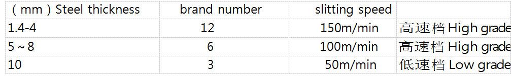
DC motor drive main reducer with brake, equipped with high speed and low speed Winding speed: plate thickness less than 8mm is greater than 100m / min. Plate thickness 10mm is greater than 50m / min
The main reduction gear box uses hard tooth surface high-precision gears, and the maximum gear modulus is M20
Coupling adopts national standard pin-pin coupling, with large bearing capacity and long life Main motor power: 160Kw/750rpm; DC motor with disk brake Shanghai Xingyang
Reel diameter:φ760mm;
Hydraulic expansion and contraction quadrangular pyramid Reel material: ZG45 surface hardened
Roll expansion and contraction:50mm;
Drum expansion and contraction method: hydraulic expansion and contraction
The reel expansion and contraction does not use a rotating oil cylinder. It adopts a rotating bearing structure, which has good stability and low failure rate.
Up and down cylinder:φ250 ;
Separation device depression: hydraulic depression Depress the oil cylinder:φ140 ;
Pushing device launched: hydraulic push Launch of oil cylinder:φ140 ; Supporting arm swinging oil cylinder:φ140
4.18.1 Function: Unload the coiled steel coil from the roll with the
pushing device, and transport it to the unloading position, and the material will be transferred by the crane.
4.18.2 composed by
The steel coil trolley is composed of a traversing trolley, a lifting device, a bearing saddle and a track.
4.18.3 parameters and structure
The traversing trolley is a welded steel structure trolley,
which is driven forward or backward by a motor. The lifting device and the bearing saddle are welded structures. The lifting device is driven by a hydraulic cylinder to riseand lower, and it has a guide column guide device.
V-platform Covered with nylon skid pads
4.18 Unloading trolley
Adapt to strip steel coil weight: max 25 t
Adapt to the outer diameter of the strip: φ800~ φ2000 mm Walking speed: 8m/min
Lifting cylinder bore: 200mm Walking motor: 4kw
4.19 2# Side guide roll
type: Vertical roll guide type
guide roll: 150mmØ x150mmH x 2 pcs x 2 sets High carbon steel, heat treated & CR coating Guide open/close : 400-1650mm , operated by AC geared motor
4.20 leveler
Type 4-Hi, 11 rolls type
Leveling speed Max 30m/min
Feeding roller:200mmØ x 1750mmL x 2 pcs. PU: PU coated
Upper roll up/down by Hydraulic cylinder
Work roll: 150mmØ x 1750mmL x 11 pcs.
Material SUJ2, heat treated and ground, hardness hrc64, chrome plated Cr coating
Support roll:160mm Ø x 3 rows 42CrMo, heat treated and ground, hardness HRC55, CR
coating
Up/down by geared motor
intermesh adjust :By AC 2.2kw X2 geared motor
-15+70mmH, Open -15+70mmH , display by digital indicator;driving unit: Drive motor – DC90kw, 1000 rpm
Gear box Universal joint shaft
Main body : Welded by steel
4.20 measuring roll Perameters:
Upper roll-95mmØ x 150mmL x 1 pcs. with encoder Special steel, heat treated and ground
Bottom roll-130mmØ x 70mmL x 1 pcs. PU coated Upper roll up/down By pneumatic cylinder
4.24.hydraulic system
Function: Provide power for the cylinder and motor of the unit Equipment composition: composed of hydraulic station and valve group
The system pressure is configured according to the area and use requirements, and placed nearby;
The hydraulic oil cooling system for the hydraulic tank outside the hydraulic station is air-cooled; The system is equipped with safety devices to prevent overload and hydraulic shock;
Hydraulic station adopts integrated block connection, and valve components are selected from Beijing Huade Genuine;
The system structure is simple and practical, the execution mechanism is stable and flexible, and the adjustment and maintenance are convenient;
The arrangement and installation of hydraulic components (devices) ensure safety and reliability, and meet the requirements of relevant safety standards and product instruction manuals; the pressure resistance of the oil cylinder is greater than 28MPa.
An oil filter is set in the system, and the filtration accuracy meets the requirements of system components;
The piping layout is neat, firm and meets the requirements, which is convenient for the disassembly of the whole machine and the maintenance and replacement of the piping; Air-cooled cooler for hydraulic station
Hydraulic solenoid valve coil voltage is DC24V
There should be a junction box at the hydraulic station and valve table, and the hydraulic valve coil is led to the junction box
Hydraulic system pressure 26MPA,
All cylinders need to withstand 28MPA pressure,
All cylinders need to be equipped with a damping structure to reduce impact 4.25 electric control system
Summery.This electrical system is designed for controlling and operating high-precision slitting project
equipment, and is a non-standard design electrical control system. The process control range is from roll-up truck to unloader.
This electrical system is mainly composed of PLC (1215C) control system, AC control system, DC speed control system, and on-site detection system. The control function of the electrical system is designed to be closely integrated with the unit process, stand-alone equipment,
and hydraulic system. Control with changes.
Total installed capacity: ~ 600 KW
Summery.
Basic control functions of electrical equipment
a. Equipment working mode selection:
The electrical system works in manual, automatic, jog, single, and linkage modes. The slitting mode includes two working modes: pull and active shear. The disc shear clutch is disengaged during the pull shear, and the coiler works alone. During the active shearing, the
disc cutter and the coiler work in conjunction with each other. The looper is used to control the disc cutter and the coiler to work at a constant linear speed. The operating parameters of the device are carried out via the touch screen.
b. Unit start and stop and emergency stop control:
The unit's No. 1 operating platform is equipped with a control power break-on button to control the control power of the entire unit. There are emergency emergency stop buttons on each operating platform. Pressing this button in the event of equipment or personal accidents
will cause the entire unit to stop.
c. Production sequence control and chain control:
The electrical system is controlled in accordance with the process of the unit and the requirements of each stand-alone device, and is equipped with various interlocks. It uses various on-site detection components (such as proximity switches, photoelectric switches, etc.) to detect and sends these signals to the PLC system. Software program controls limit, speedand interlock.
HMI basic functions
The touch screen adopts Siemens (KTP1200 Basic), which has the following functions:
a. With high-definition color screen (industrial LCD)
b. Flexible and convenient multi-screen design and screen switching operation
c. Dynamic display of the control system's overall and local equipment working status
d. Display and record of system faults and alarm signals
e. Monitoring of limit switch signals
Electrical information
a. Drawings, checklists, instructions Including electrical equipment schematic diagrams, components (model, specifications, installed capacity, manufacturers) list, switch cabinets, control cabinets, control boxes, operation site site layout and basic condition diagrams, field installation electrical pipeline diagrams, cable
tables ( Type, variety, quantity) and other technical documents required for on-site installation and maintenance, manuals and certificates of outsourced equipment and components.
b. Software and programs Provide all PLC, HMI, PC manuals and related software with authorized system software, programming software, etc .; PLC ladder diagrams, HMI, PC and CNC application software source code programs. All application blocks and atabases that access data should not be restricted by passwords.
Provide programming debugging tools, a set of system programming software and a full set of equipment procedures, all electrical drawings and documents (three copies of paper documents).
a. Power supply: three-phase four wire, AC380V ± 10%
Three phase unbalance rate ≤ 3%
b. Power supply frequency: 50Hz ± 1%
c. Grounding mode: TN-C-S
d. Ambient temperature 25 ° C ± 5
e. Ambient humidity: ≤ 85%, condensation is not allowed
Electrical technical conditions:
a. Power supply: three-phase four-wire, AC380V ± 10%
Three-phase unbalance rate
b. Power supply frequency: 50Hz ± 1%
c. Grounding method: TN-C-S
d. Ambient temperature 25 ° C ± 5
e. Ambient humidity: ≤85%, no condensation is allowed
V. INSTALLATION
The seller will arrange engineers(4 persons) go to buyer factory in batches,the buyer should pay for the engineer USD 100.00 one person one day(in 80 days),and supply the round airtickets,local cost such as the food,hotel and onthers. The commissioning will need 4 persons 80 days for installation.
Due to the buyer responsibility,delay the debugging time,the delay time,buyer should pay for the engineer USD 120.00 one person one day(after 80 days).
Slitting and cut to length line is one of the main products of Hebei Tengtian Welded Pipe Equipment Manufacturing Co., Ltd. with good quality and Cheapest.Our factory is a professional suppliers and Manufacturers china ,Wholesale prices are available for customized products.
About us

New Full Automation
The company has a strong technical ability, strong business ability, vibrant team. Through the unremitting efforts of all staff, in recent years the company has occupied most of the domestic market, and exported to Korea, Vietnam, Indonesia, South Africa, Kazakhstan and other dozens of countries and regions, from domestic and foreign customers.
Qualification


Our Services
1.) We will send the engineer for the installation and training your workers how to operate this machine in correct way.
2.) Warranty Team
One year quality guarantee, life guarantee repair. Within quality guarantee period, except for failures caused by human error, repair parts will be provided for free. After the quality guarantee period, only charge the cost of the spare parts.
3.) We supply the pre-sell and after-sell service.
pre-sell service: workshop design, and production output design
after-sell service: installation and training, and the skilled engineer for working.
4.) We can also sent the engineer working for you serval months or 1 year. The engineer will help you to improve the output, reduce the waste and decrease the cost.
5.) We supply the pre-sell service-Design for whole project for stainless steel pipe making/ carbon steel pipe making.
6.) We will be responsible for the loading and shipping .


Our customers
Our company specializes in the production of pipe mill, slitting line,cold roll forming,stainless steel pipe mill and other equipment,On the basis of the introduction of the advanced technology of Japan, the company is innovative and the machine are manufactured in strict accordance with the standard of Japan.Advanced configuration,stable quality,excellent performance,with excellent market visibility and reputation,our machine has reached the world's leading level.

Exhibition


Packing and shipping
Our equipment has been exported to dozens of countries and regions such as Egypt, Greece,South Korea,Vietnam,Indonesia,South Africa,etc.,and received favorable comments from domestic and foreign customers.


Contact us
Hebei Tengtian Welded Pipe Equipment Manufacturing Co., Ltd.
Add:No.15,Shanqian Road,Economic Development Zone,Hebei,China
Mobile Number:+86 18233100172
Tel:+86-311-83025332
Email:pipemill@sjzztsd.com

Previous:
Next:
Product inquiry
Related products


WhatsApp/Wechat
INQUIRY